Update: the version with working SPI DMA
The Intel Edison doesn’t have a video interface; so, you connect an OLED or TFT LCD display via the SPI interface using the Linux kernel video module framebuffer.
I used fbtft – Linux Framebuffer drivers for small TFT LCD display modules by Noralf Tronnes.
My display is 2.8″ OLED Display 256×64 Graphic Module SSD1322.
After reading the documentation for the display, I connected it to the Edison via the 4-wire SPI interface, which requires an additional GPIO pin for the D/C signal (Write Data/Write Command). The 3-wire SPI interface uses the 9 bit SPI interface and should be avoided.
I compared the timing diagrams for the SSD1322 chip with the SPI Transfer Modes and found that it uses the SPI Mode 3.
Schematic
Here is the schematic of my SSD1322 shield for the Intel Edison.
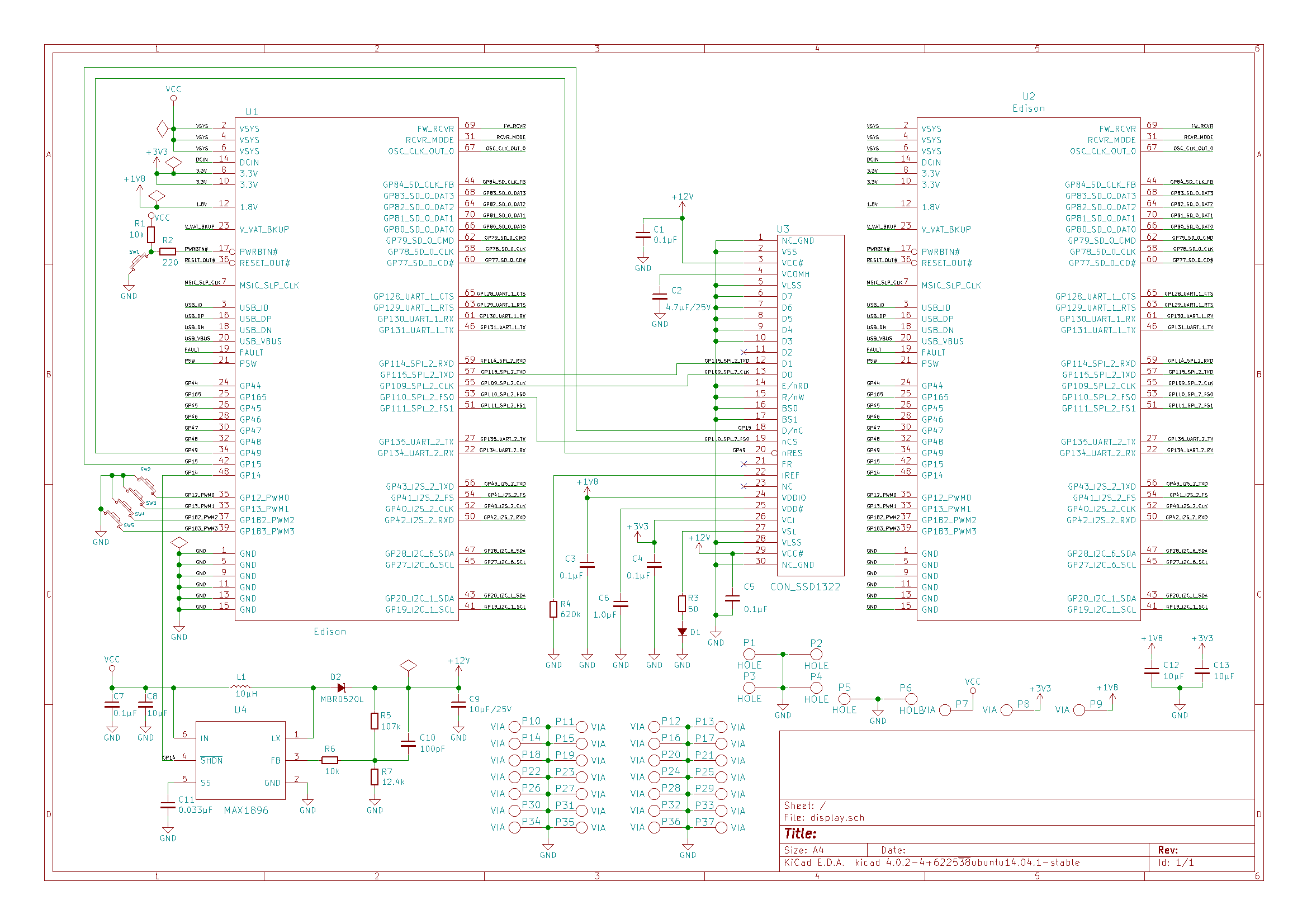
Connections between the Edison and the Display:
GP49 -> RES(Reset Signal Input)
GP15 -> D/C(Data/Command Control)
GP110_SPI_2_FS0(CS0) -> CS(Chip Select Input)
GP109_SPI_2_CLK -> D0/SCLK(Serial Clock)
GP115_SPI_2_TXD -> D1/SDIN(Serial Data Input)
I also connected GP14 to the SHDN pin of the +12V voltage regulator.
fbtft download and configuration
The latest code from the notro/fbtft repository didn’t work for me.
I used the older code presslab-us/fbtft, which also included support for my chip SSD1322.
I prepared the Edison directory with the Linux sources as described in my article Building Yocto Linux for Intel Edison.
After I compiled the Edison image for the first time, I copied these two hidden directories into another folder (I placed the Edison sources into the “edison” directory in my home directory); so, I can return the sources to the original state by copying these hidden directories back at any moment.
~/edison/edison-src/build/tmp/work/edison-poky-linux/linux-yocto/3.10.17-r0/linux/.git
~/edison/edison-src/build/tmp/work/edison-poky-linux/linux-yocto/3.10.17-r0/linux/.meta
I created the directory “fbtft” and copied all fbtft files there.
mkdir ~/edison/edison-src/build/tmp/work/edison-poky-linux/linux-yocto/3.10.17-r0/linux/drivers/video/fbtft
I added the line in ~/edison/edison-src/build/tmp/work/edison-poky-linux/linux-yocto/3.10.17-r0/linux/drivers/video/Kconfig before the line “endmenu”.
source "drivers/video/fbtft/Kconfig"
I added the line in ~/edison/edison-src/build/tmp/work/edison-poky-linux/linux-yocto/3.10.17-r0/linux/drivers/video/Makefile
obj-$(CONFIG_FB_TFT) += fbtft/
Then I edited the file ~/edison/edison-src/build/tmp/work/edison-poky-linux/linux-yocto/3.10.17-r0/linux/drivers/video/fbtft/fbtft_device.c
I added the header
#include <linux/spi/intel_mid_ssp_spi.h>
Then I added the description of my display into the list of displays.
Where “reset” uses the number 49 of the GP49 pin, “dc” is GP15.
The pin “led” is GP14 and I use it in my custom initialization code in the file fb_ssd1322.c
DMA has to be disabled because the DMA code in intel_mid_ssp_spi.h is broken.
If you enable it, you can see errors like this: “intel_mid_ssp_spi_unified 0000:00:07.1: ERROR : DMA buffers already mapped”
{
   .name = "er_oled028",
   .spi = &(struct spi_board_info) {
       .modalias = "fb_ssd1322",
       .max_speed_hz = 12000000,
       .mode = SPI_MODE_3,
       .bus_num = 5,
       .chip_select = 0,
       .controller_data = &(struct intel_mid_ssp_spi_chip) {
           .burst_size = DFLT_FIFO_BURST_SIZE,
           .timeout = DFLT_TIMEOUT_VAL,
           .dma_enabled = false,
        },
        .platform_data = &(struct fbtft_platform_data) {
           .display = {
               .buswidth = 8,
               .backlight = 0,
               .width = 256,
               .height = 64,
           },
           .gpios = (const struct fbtft_gpio []) {
               { "reset", 49 },
               { "dc", 15},
               { "led", 14},
               {},
           },
       }
   }
},
I wrote my custom initialization code for the display ER_OLED028 in fb_ssd1322.c following the documentation for my display.
static int init_display(struct fbtft_par *par)
{
   fbtft_par_dbg(DEBUG_INIT_DISPLAY, par, "%s()\n", __func__);

   //reset the chip
   mdelay(5);
   fbtft_par_dbg(DEBUG_RESET, par, "%s()\n", __func__);
   gpio_set_value(par->gpio.reset, 0);
   udelay(200);
   gpio_set_value(par->gpio.reset, 1);
   udelay(200);

   write_reg(par, 0xfd, 0x12); /* Unlock OLED driver IC */
   write_reg(par, 0xae); /* Display Off */
   write_reg(par, 0xb3, 0x91); /* Display divide clockratio/frequency */
   write_reg(par, 0xca, 0x3f); /* Multiplex ratio, 1/64, 64 COMS enabled */
   write_reg(par, 0xa2, 0x00); /* Set offset, the display map starting line is COM0 */
   write_reg(par, 0xa1, 0x00); /* Set start line position */
   write_reg(par, 0xa0, 0x14, 0x11); /* Set remap, horiz address increment, disable colum address remap, */
				                      /*  enable nibble remap, scan from com[N-1] to COM0, disable COM split odd even */
   write_reg(par, 0xb5, 0x00); /* Set GPIO */
   write_reg(par, 0xab, 0x01); /* Select internal VDD */
   write_reg(par, 0xb4, 0xa0, 0xfd); /* Display enhancement A, external VSL, enhanced low GS display quality */
   write_reg(par, 0xc1, 0xff); /* Contrast current, 256 steps, default is 0x7F */
   write_reg(par, 0xc7, 0x0f); /* Master contrast current, 16 steps, default is 0x0F */
   write_reg(par, 0xb1, 0xe2); /* Phase Length */
   write_reg(par, 0xd1, 0x82, 0x20); /* Display enhancement B */
   write_reg(par, 0xbb, 0x1f); /* Pre-charge voltage */
   write_reg(par, 0xb6, 0x08); /* Set Second Pre-Charge Period */
   write_reg(par, 0xbe, 0x07); /* Set VCOMH */
   write_reg(par, 0xa6); /* Normal display */

   //enable VCC
   gpio_set_value(par->gpio.led[0], 1);
   mdelay(100);

   write_reg(par, 0xaf); /* Display ON */

   return 0;
}
After all modifications, I created a patch file.
While committing to git, I added the comment line “fbtft_ssd1322″.
cd ~/edison/edison-src/build/tmp/work/edison-poky-linux/linux-yocto/3.10.17-r0/linux/drivers/video
git add .
git commit
git format-patch -1
It created the patch file “0001-fbtft_ssd1322.patch”. I renamed it to “fbtft_ssd1322.patch” and copied it to:
~edison/edison-src/meta-intel-edison/meta-intel-edison-bsp/recipes-kernel/linux/files/
I created the kernel configuration file fbtft.cfg in the same directory “recipes-kernel/linux/files/”:
CONFIG_FRAMEBUFFER_CONSOLE=m
CONFIG_FRAMEBUFFER_CONSOLE_DETECT_PRIMARY=m
CONFIG_FB_SYS_FILLRECT=y
CONFIG_FB_SYS_COPYAREA=y
CONFIG_FB_SYS_IMAGEBLIT=y
CONFIG_FB_SYS_FOPS=y
CONFIG_FB_DEFERRED_IO=y
CONFIG_FB_BACKLIGHT=y
CONFIG_FB_TFT=m
# CONFIG_FB_TFT_GU39XX is not set
# CONFIG_FB_TFT_HX8340BN is not set
# CONFIG_FB_TFT_HX8347D is not set
# CONFIG_FB_TFT_ILI9320 is not set
# CONFIG_FB_TFT_ILI9325 is not set
# CONFIG_FB_TFT_ILI9341 is not set
# CONFIG_FB_TFT_PCD8544 is not set
# CONFIG_FB_TFT_SSD1289 is not set
# CONFIG_FB_TFT_SSD1351 is not set
CONFIG_FB_TFT_SSD1322=m
# CONFIG_FB_TFT_ST7735R is not set
# CONFIG_FB_FLEX is not set
CONFIG_FB_TFT_FBTFT_DEVICE=m
# CONFIG_TOUCHSCREEN_ADS7846_DEVICE is not set
I commented the line in the file board.c for the device ads7955 that occupies the same SPI busnum=5, cs=0 that we use for the display.
Then I ran the same git sequence to generate the patch file “platform_ssd1322.patch” and copied it into the same “recipes-kernel/linux/files” directory.
From c83f14b37bc2dcfa97b36214f02b15ddaad51a47 Mon Sep 17 00:00:00 2001
From: Farit <farit@example.com>
Date: Sat, 9 Apr 2016 22:02:19 -0700
Subject: [PATCH] platform_ssd1322

---
 arch/x86/platform/intel-mid/board.c | 2 +-
 1 file changed, 1 insertion(+), 1 deletion(-)

diff --git a/arch/x86/platform/intel-mid/board.c b/arch/x86/platform/intel-mid/board.c
index eb3d8a4..fca6440 100644
--- a/arch/x86/platform/intel-mid/board.c
+++ b/arch/x86/platform/intel-mid/board.c
@@ -111,7 +111,7 @@ struct devs_id __initconst device_ids[] = {

 	/* SPI devices */
 	{"spidev", SFI_DEV_TYPE_SPI, 0, &spidev_platform_data, NULL},
-	{"ads7955", SFI_DEV_TYPE_SPI, 0, &ads7955_platform_data, NULL},
+//	{"ads7955", SFI_DEV_TYPE_SPI, 0, &ads7955_platform_data, NULL},
 	{"bma023", SFI_DEV_TYPE_I2C, 1, &no_platform_data, NULL},
 	{"pmic_gpio", SFI_DEV_TYPE_SPI, 1, &pmic_gpio_platform_data, NULL},
 	{"pmic_gpio", SFI_DEV_TYPE_IPC, 1, &pmic_gpio_platform_data,
--
1.9.1
When all patch and configuration files were ready, I added links to them into the file “~/edison/edison-src/meta-intel-edison/meta-intel-edison-bsp/recipes-kernel/linux/linux-yocto_3.10.bbappend”.
SRC_URI += "file://defconfig"
SRC_URI += "file://upstream_to_edison.patch"

SRC_URI += "file://fbtft.cfg"
SRC_URI += "file://fbtft_ssd1322.patch"
SRC_URI += "file://platform_ssd1322.patch"
fbtft Module Compilation
Then I recompiled the Linux image and installed it.
cd ~/edison/edison-src
source poky/oe-init-build-env
bitbake edison-image
~/edison/edison-src/meta-intel-edison/utils/flash/postBuild.sh
~/edison/edison-src/build/toFlash/flashall.sh
Loading and Testing the Framebuffer Module
I loaded the fbtft module supplying the name of the display and the SPI bus number (it’s 5 on the Edison).
modprobe fbtft_device name=er_oled028 busnum=5
Sometimes, it’s not loaded. I need to investigate the problems.
When it loads, the “dmesg” command shows:
[   32.254181] fbtft_device:  GPIOS used by 'er_oled028':
[   32.254205] fbtft_device:    'reset' = GPIO49
[   32.254221] fbtft_device:    'dc' = GPIO15
[   32.254234] fbtft_device:    'led' = GPIO14
[   32.254246] fbtft_device:  SPI devices registered:
[   32.254264] fbtft_device:      spidev spi5.1 25000kHz 8 bits mode=0x00
[   32.254281] fbtft_device:      fb_ssd1322 spi5.0 12500kHz 8 bits mode=0x03
[   32.394493] graphics fb0: fb_ssd1322 frame buffer, 256x64, 32 KiB video memory, 8 KiB buffer memory, fps=20, spi5.0 at 12 MHz
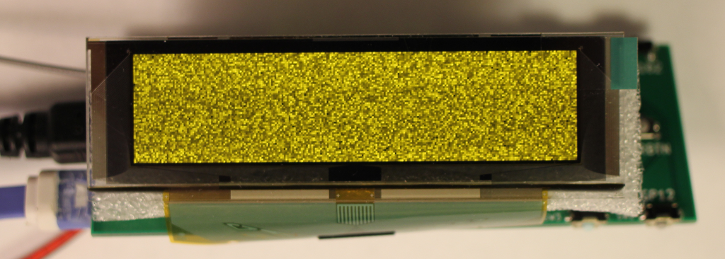
Then I can test the module by sending random values to the framebuffer socket “/dev/fb0″.
cat /dev/urandom > /dev/fb0
Here is the result.
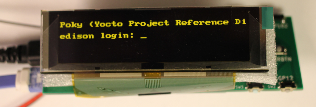
I can also load the fbcon module to display the console on the display.
modprobe fbcon
Improvements
There are patches on the Edison forum that may help to fix the DMA issue. Otherwise, the display will be relatively slow.
Check this link stewart maguire’s patches for DMA and FBTFT support.
And this Intel MID SSP SPI driver getting stuck in kernel space.
Hardware Setup
Confirm SPI Mode 3 (CPOL=1, CPHA=1) matches your OLED spec.
Wiring should include:
GP49 → RESET
GP15 → D/C (Data/Command)
SPI2_CLK → SCLK
SPI2_TXD → SDIN
CS0 → Chip Select
For Maclight’s 2.08″ OLED: Verify if additional pins (e.g., VCC enable) are needed.
https://www.szmaclight.com/2-08-inch-oled-module-display-256×64-sh1122.html
Driver Configuration
Use the presslab-us/fbtft fork (SSD1322 support included).
Critical edits in fbtft_device.c:
Disable DMA (dma_enabled=false) due to Intel Edison limitations.
Customize init_display() for your panel (timings/commands may vary).
Kernel config must enable:
config
CONFIG_FB_TFT_SSD1322=m
CONFIG_FB_TFT_FBTFT_DEVICE=m
SPI Bus Conflict Resolution
Disable conflicting devices (e.g., comment out ads7955 in board.c if using SPI bus 5).
Apply patches via Yocto (linux-yocto_3.10.bbappend).
Testing
Load module:
bash
modprobe fbtft_device name=er_oled028 busnum=5
Validate with dmesg | grep fb0 for successful registration.
Test display:
bash
cat /dev/urandom > /dev/fb0 # Random noise test
For Maclight 2.08″ OLED:
Model Differences: Confirm if it uses SSD1322 (check datasheet). Adjust resolution in fbtft_platform_data if needed (e.g., 256×64 vs 128×32).
SPI Speed: Reduce max_speed_hz (e.g., 8MHz) if artifacts occur.
Backlight Control: Map an unused GPIO to led in fbtft_gpio[] if the panel has enable logic.
Debug Tips:
If module fails to load:
bash
dmesg | tail -20 # Check for SPI/GPIO errors
lsmod | grep fbtft # Verify module dependencies
For blank screen: Double-check init_display() sequence against your OLED’s datasheet.
Let me know if you need help adapting this to Maclight’s specific pinout or initialization sequence!
This response is:
✅ Structured – Clear sections for hardware/software steps.
✅ Actionable – Includes commands and config snippets.
✅ Adaptable – Notes where Maclight-specific changes may apply.
✅ Concise – Avoids unnecessary technical digressions.
Would you like me to elaborate on any section?