If you want to create a graphical user interface (GUI) for the Intel Edison, it’s better to use the popular Qt cross-platform framework.
Then you will be able to develop and debug a program on your powerful desktop computer and then deploy it to your Edison and test it there.
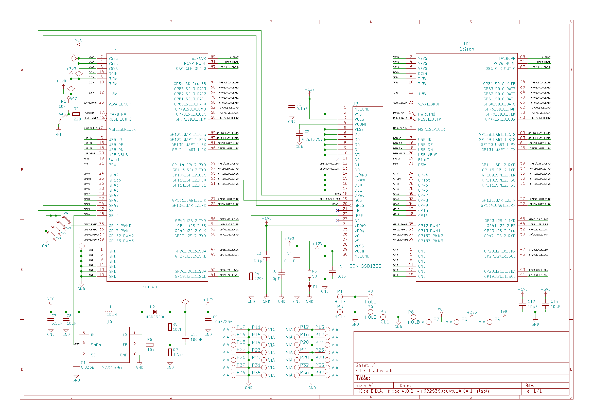
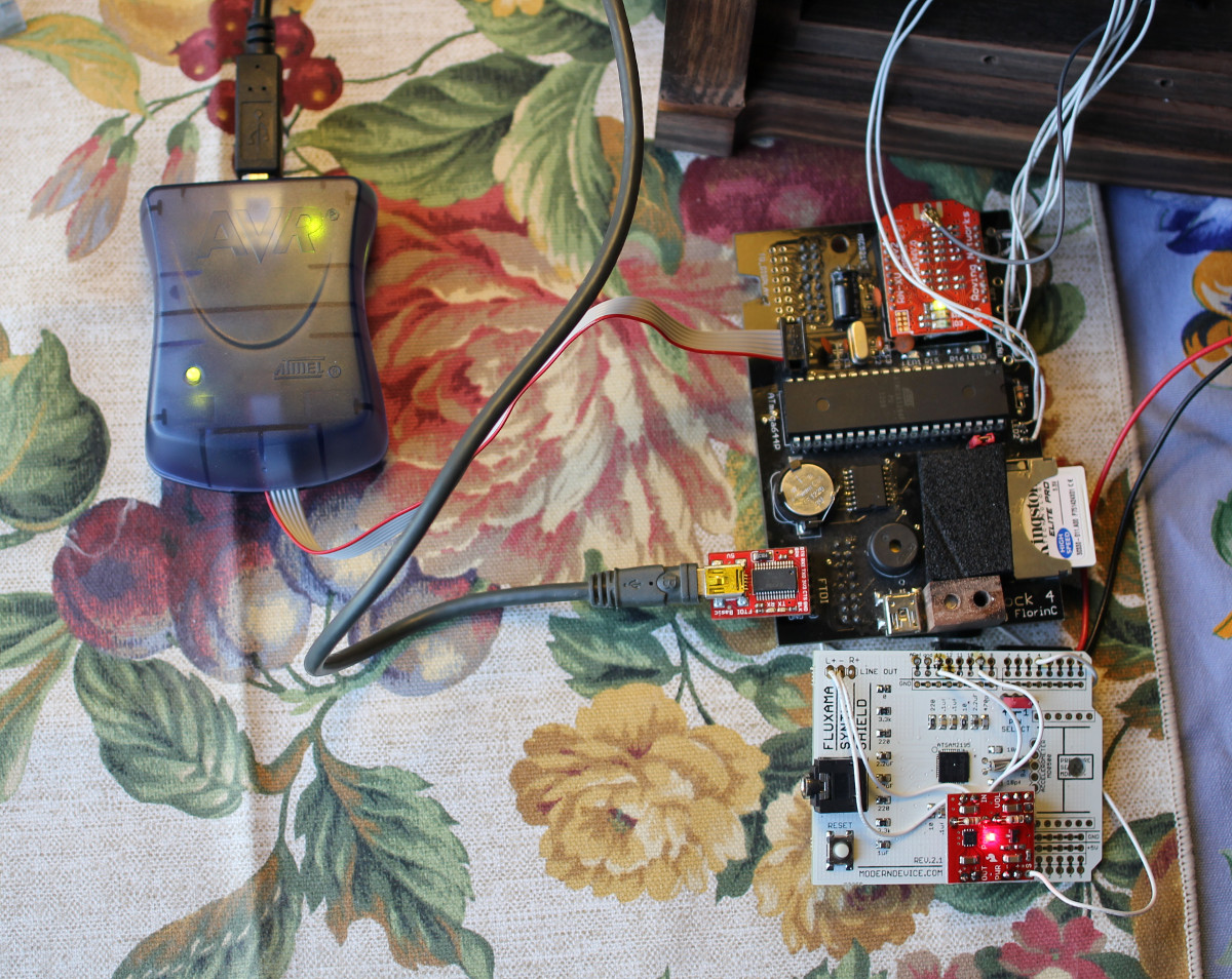
My hardware and Linux kernel configuration
I used my shield that has a SSD1322 based display connected to the SPI bus and 4 push buttons connected to GPIOs.
The display is controlled through the Linux framebuffer kernel module fbtft.
The buttons are controlled through the gpio-keys module.
QT5 Yocto Client package installation
My Edison source packages are located in the folder ~/edison.
I increased the size of my root Edison partition in the file ~/edison/poky/meta-intel-edison/meta-intel-edison-distro/recipes-core/images/edison-image.bb
IMAGE_ROOTFS_SIZE = "1048576"
I downloaded a new meta package meta-qt5.
At the time of writing, the Intel Edison packages used the openembedded branch called “dizzy”.
cd ~/edison/poky
git clone -b dizzy https://github.com/meta-qt5/meta-qt5.git
I modified the configuration file ~/edison/build_edison/conf/auto.conf
I added some Qt packages and enabled some configuration options. I may select something else in the future.
The Intel Edison has no GPU. So, the Qt OpenGL based modules don’t work. Among them are Qt Quick and Qt Declarative and the packages that depend on these two.
DISTRO = "poky-edison"
MACHINE = "edison"
DISTRO_FEATURES_append = " alsa bluetooth x11"
PACKAGE_CLASSES = "package_ipk"
BB_DANGLINGAPPENDS_WARNONLY = "1"
EDISONREPO_TOP_DIR = "${TOPDIR}/../poky"

IMAGE_INSTALL_append = " tinyb"
IMAGE_INSTALL_append = " tinyb-dev"
#IMAGE_INSTALL_append = " openzwave"
IMAGE_INSTALL_append = " bacnet-stack"
IMAGE_INSTALL_append = " libmodbus"
IMAGE_INSTALL_append = " mc"
IMAGE_INSTALL_append = " qtbase qtbase-fonts \
    qtbase-plugins \
    qtbase-tools \
    qtimageformats-plugins"
IMAGE_INSTALL_append_core2-32 = " libft4222"
IMAGE_INSTALL_append_edison = " libft4222"
LICENSE_FLAGS_WHITELIST_append = " ftdi"
GCCVERSION = "4.9%"

PACKAGECONFIG_DISTRO_append_pn-qtbase = " linuxfb icu alsa pulseaudio sql-sqlite"
I modified the file ~/edison/build_edison/conf/bblayers.conf and added the meta-qt5 layer at the end of BBLAYERS.
LCONF_VERSION = "6"

BBPATH = "${TOPDIR}"
BBFILES ?= ""

BBLAYERS ?= " \
  ${TOPDIR}/../poky/meta \
  ${TOPDIR}/../poky/meta-intel-edison/meta-intel-arduino \
  ${TOPDIR}/../poky/meta-intel-edison/meta-intel-edison-bsp \
  ${TOPDIR}/../poky/meta-intel-edison/meta-intel-edison-distro \
  ${TOPDIR}/../poky/meta-intel-iot-devkit \
  ${TOPDIR}/../poky/meta-intel-iot-middleware \
  ${TOPDIR}/../poky/meta-java \
  ${TOPDIR}/../poky/meta-oic \
  ${TOPDIR}/../poky/meta-openembedded/meta-filesystems \
  ${TOPDIR}/../poky/meta-openembedded/meta-networking \
  ${TOPDIR}/../poky/meta-openembedded/meta-oe \
  ${TOPDIR}/../poky/meta-openembedded/meta-python \
  ${TOPDIR}/../poky/meta-openembedded/meta-ruby \
  ${TOPDIR}/../poky/meta-openembedded/meta-webserver \
  ${TOPDIR}/../poky/meta-yocto \
  ${TOPDIR}/../poky/meta-yocto-bsp \
  ${TOPDIR}/../poky/meta-qt5 \
  "
BBLAYERS_NON_REMOVABLE ?= " \
  ${TOPDIR}/../poky/meta \
  ${TOPDIR}/../poky/meta-yocto \
  "
Then the usual Edison image compilation stage.
You must insert yourself into the group “dialout” on Linux Ubuntu to have permissions to run the script “flashall.sh”.
cd ~/edison/poky/
source oe-init-build-env ../build_edison/
bitbake edison-image u-boot
../poky/meta-intel-edison/utils/flash/postBuild.sh .
./toFlash/flashall.sh
Qt5 Host cross-platform SDK compilation
I modified the file ~/edison/poky/meta-qt5/recipes-qt/packagegroups/packagegroup-qt5-toolchain-target.bb
and deleted all packages from the list RDEPENDS_${PN} that depend on Qt Quick and Qt Declarative. My list may change in the future.
RDEPENDS_${PN} += " \
    packagegroup-core-standalone-sdk-target \
    libsqlite3-dev \
    qtbase-dev \
    qtbase-fonts \
    qtbase-mkspecs \
    qtbase-plugins \
    qtbase-staticdev \
    qtconnectivity-dev \
    qtconnectivity-mkspecs \
    qtimageformats-dev \
    qtimageformats-plugins \
    qtserialport-dev \
    qtserialport-mkspecs \
    qtsvg-dev \
    qtsvg-mkspecs \
    qtsvg-plugins \
    qtsystems-dev \
    qtsystems-mkspecs \
    qttools-dev \
    qttools-mkspecs \
    qttools-staticdev \
    qttools-tools \
    qtxmlpatterns-dev \
    qtxmlpatterns-mkspecs \
"
I compiled the SDK.
cd ~/edison/poky/
source oe-init-build-env ../build_edison/
bitbake meta-toolchain-qt5
I ran the new SDK installer in ~/edison/build_edison/tmp/deploy/sdk
sh poky-edison-glibc-x86_64-meta-toolchain-qt5-core2-32-toolchain-1.7.3.sh
It installed the SDK into the default folder /opt/poky-edison/1.7.3
I opened the directory /opt/poky-edison/1.7.3/sysroots/x86_64-pokysdk-linux/usr/bin/i586-poky-linux
and created symlinks. Without them, my system compiler and linker in /usr/bin are called instead.
ln -s i586-poky-linux-g++ g++
ln -s i586-poky-linux-cpp cpp
ln -s i586-poky-linux-ld ld
ln -s i586-poky-linux-gdb gdb
Qt Creator IDE installation
I installed Qt Creator from https://download.qt.io/archive/qt/5.3/5.3.2/, as the version of Qt in the Yocto package is 5.3.2.
But, probably, the one from the Linux distribution should work as well.
I installed it in the directory ~/Qt.
I modified the script ~/Qt/Tools/QtCreator/bin/qtcreator.sh, so it will load the environment variables for the SDK. I put the new line at the very top of the script.
source /opt/poky-edison/1.7.3/environment-setup-core2-32-poky-linux
#! /bin/sh
On my Edison I created the user “farit” and added him to the group “video” that has permissions to write to the framebuffer and read input buttons. His home directory on the Edison is “/home/farit”.
usermod -a -G video farit
I modified the menu link on my desktop to run the script ~/Qt/Tools/QtCreator/bin/qtcreator.sh to open Qt Creator.
In Qt Creator, I opened the menu Tools -> Options -> Devices and added my Edison device as “Generic Linux Device”.
I named it “edison” and provided the name and password combination for the user “farit”. Then tested the connection.
I opened the menu Tools > Options > Build & Run.
I opened the tab “Qt Versions”, clicked on the button “Add” and browsed to select qmake
/opt/poky-edison/1.7.3/sysroots/x86_64-pokysdk-linux/usr/bin/qt5/qmake
I opened the tab “Compilers”, clicked on the button “Add”, selected “GCC” and browsed to select gcc
/opt/poky-edison/1.7.3/sysroots/x86_64-pokysdk-linux/usr/bin/i586-poky-linux/i586-poky-linux-gcc
I opened the tab “Debuggers”, clicked on the button “Add” and browsed to select gdb. I named it GDB.
/opt/poky-edison/1.7.3/sysroots/x86_64-pokysdk-linux/usr/bin/i586-poky-linux/i586-poky-linux-gdb
I opened the tab “Kits”, clicked on the button “Add” and filled in the form.
I selected the values for Qt, Compiler, Debugger that I just defined in the previous steps.
Name: edison
Device type: Generic Linux Device
Device: edison
Sysroot: /opt/poky-edison/1.7.3/sysroots/x86_64-pokysdk-linux
Compiler: GCC
Debugger: GDB
Qt Version: Qt 5.3.2
Sample Qt program
I clicked on “New Project” and selected Applications -> Qt Widgets Application.
I named it “testik”.
In testik.pro, I added the path “/home/farit”, where Qt Creator will copy the executable on the Edison.
#-------------------------------------------------
#
# Project created by QtCreator 2016-06-02T14:32:35
#
#-------------------------------------------------

QT       += core gui

greaterThan(QT_MAJOR_VERSION, 4): QT += widgets

TARGET = testik
TEMPLATE = app


SOURCES += main.cpp\
        mainwindow.cpp

HEADERS  += mainwindow.h

FORMS    += mainwindow.ui

target.path = /home/farit
INSTALLS += target
In mainwindow.h, I only added the prototype for the function “keyPressEvent”.
#ifndef MAINWINDOW_H
#define MAINWINDOW_H

#include <QMainWindow>

namespace Ui {
class MainWindow;
}

class MainWindow : public QMainWindow
{
    Q_OBJECT

public:
    explicit MainWindow(QWidget *parent = 0);
    ~MainWindow();

protected:
    void keyPressEvent(QKeyEvent *);

private:
    Ui::MainWindow *ui;
};

#endif // MAINWINDOW_H
main.cpp is the default one
#include "mainwindow.h"
#include <QApplication>

int main(int argc, char *argv[])
{
    QApplication a(argc, argv);
    MainWindow w;
    w.show();

    return a.exec();
}
In mainwindow.cpp, I implemented the function “keyPressEvent”.
#include <QKeyEvent>
#include <QDebug>
#include "mainwindow.h"
#include "ui_mainwindow.h"

MainWindow::MainWindow(QWidget *parent) :
    QMainWindow(parent),
    ui(new Ui::MainWindow)
{
    ui->setupUi(this);
}

MainWindow::~MainWindow()
{
    delete ui;
}

void MainWindow::keyPressEvent(QKeyEvent *event)
{
    if(event->key() == Qt::Key_Up)
    {
        if (event->isAutoRepeat()) {
             ui->myLabel->setText("You auto pressed Up");
        }
        else {
            ui->myLabel->setText("You pressed Up");
        }
    }
    else if(event->key() == Qt::Key_Down)
    {
        ui->myLabel->setText("You pressed Down");
    }
}
In mainwindow.ui, I created a label “myLabel”.
In the MainWindow properties, I clicked on the “palette” button and made the background transparent by setting the opacity to 0 for “Window”. I changed “WindowText” to white by selecting the color #FFFFFF.
In the “Projects” tab in the “Run” section, I added the arguments for the executable, so it can write to the default framebuffer /dev/fb0 and read input from /dev/input/event0.
-platform linuxfb -plugin EvdevKeyboard