Zephyr Real-Time Operating System
When you have a powerful microcontroller, there is no need to limit yourself by the capabilities of Arduino. Most Arduino programs run in a loop that checks buttons, does some calculations, connect to the Internet, etc sequentially. Coding gets complicated when you want to click on a button and process the click quickly while another function is slowly connecting and parsing a webpage.
A Real-Time operating system allows to code multiple functions and delegate the task of running them simultaneously to the OS.
Zephyr Project is a very promising project. But some sensors, displays, hardware chips don’t have drivers to interact with them yet.
An experienced programmer usually learns by reading code of sample programs. Zephyr provides many samples.
STM32 Nucleo boards
ST provides $15 evaluation boards for its family of the STM32 ARM processors called Nucleo.
I compared the list of available Nucleo boards with the list of the Nucleo boards supported by Zephyr.
I wanted a low-power microcontroller with the largest RAM and flash, and in the LQFP64 package (64 pins, 10×10 mm), which is hot-air solderable. I selected ST Nucleo L452RE for the project.
How the Holtek HT1632C works
The Holtek HT1632C is a popular display controller that can drive matrices of LEDs (one chip up to 32×8 or 24×16). The Holtek HT1632D is a newer version that can come in a smaller LQFP48 7×7 mm package that has fewer pins for rows.
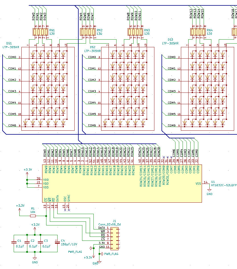
Here is a typical electrical schema. The HT1632C controls the 5×7 LED matrices (with 1 additional row for a dot) with the common cathodes.
Here is how it works. To turn on the 1st top LED in the 2nd column, the HT1632C sets 1 (HIGH) on ROW1 and opens COM0, so the current flows via the current-limiting resistor to the LED and then via COM0 to the ground. The LED turns on.
The LEDs in the matrices are addressed starting from the leftest top LED.
In order to enable the 1st top LED in the 2nd column, user code must write 1 into the HT1632C RAM address matching the ROW1 and COM0 combination. According to the HT1632C controller datasheet, the address is 02H when the controller is configured as 32 ROW x 8 COM or the address is 04H when the controller is configured as 24 ROW x 16 COM.
The HT1632C communication protocol
The HT1632C uses 4 pins to communicate with a microcontroller.
- CS (chip select)
- WR (write)
- RD (read)
- DATA
This driver doesn’t read from the display controller. It only writes. So, we don’t use the RD pin.
- The CS pin is active LOW. When the microcontroller wants to communicate with the HT1632C, it sets the CS pin to the ground (LOW).
- The microcontroller sets the WR pin to LOW.
- It sends a bit (0 or 1) by setting the DATA pin to LOW (0) or HIGH (1).
- It sets the WR pin to HIGH. The HT1632C reads the DATA bit on the rising WR edge.
- The microcontroller repeats the WR LOW, DATA bit, WR HIGH sequence until all bits are sent.
- When it finishes, it sets the CS pin HIGH.
There are two modes of operation: the command mode and the write data mode.
The command mode starts with the 3 bits 100 and then the command itself.

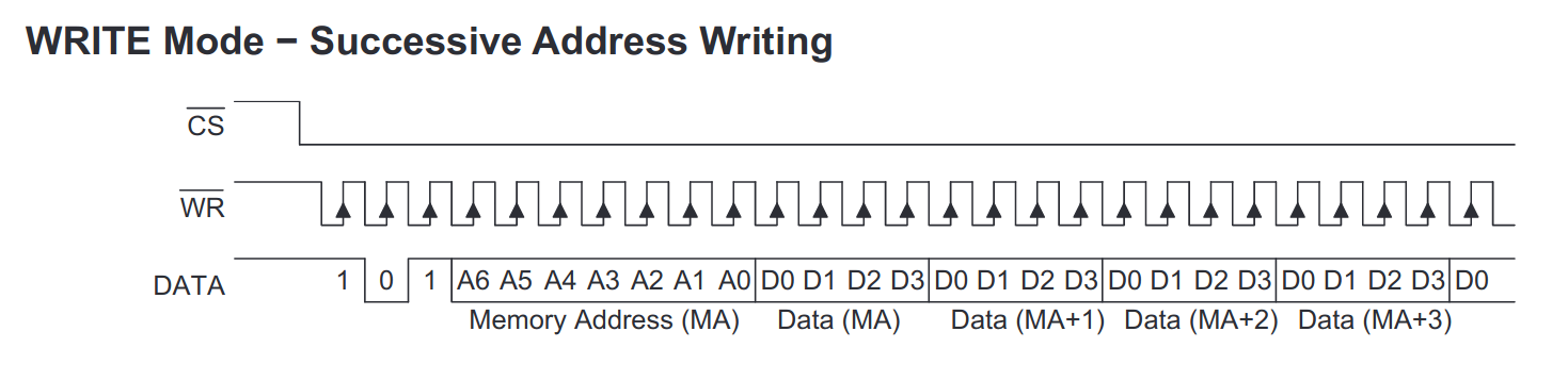
The write data mode starts with the 3 bits 101, the RAM address, the 4 bits of data.
This driver writes the whole array of data starting from the address 00H using the Successive Address Writing Mode. It starts with the 3 bits 101, the RAM address 00H, then all 32 8-bit words or 24 16-bit words.
It’s the task of the application code to set individual bits in the matrix array. Then it sends the whole matrix array to the driver.
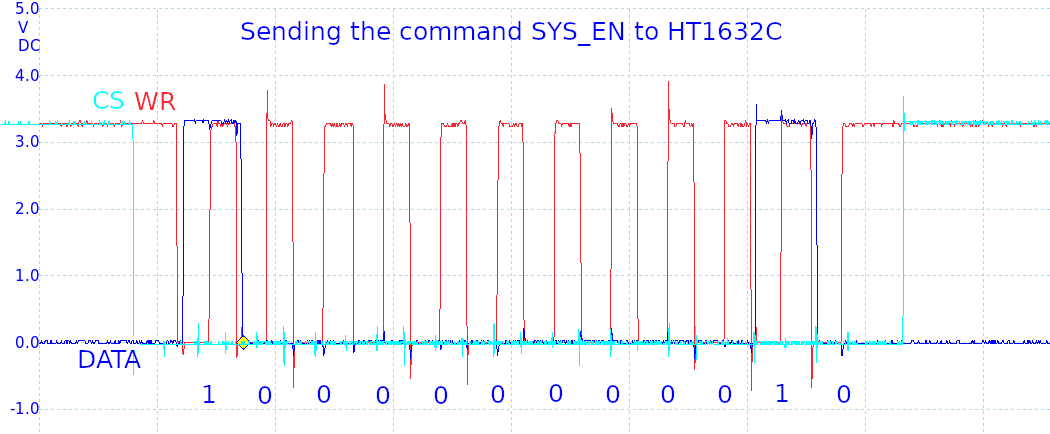
Here is how the command SYS EN (Turn on system oscillator) looks like on the screen of my oscilloscope.
SYS EN 100-0000-0001-0
Zephyr Application Structure
The structure of my application is based on the Zephyr Example Application.
It creates an application with a sensor driver.
I changed the string ‘example-application’ in the files to my own application name.
HT1632C Zephyr Driver Installation
Download the source from https://github.com/faritka/zephyr-ht1632c and follow instructions there.
Zephyr driver configuration files
Available configuration options are defined in the file dts/bindings/display/holtek,ht1632c.yaml.
It follows the Device Tree specifications.
The GPIOS have the phandle-array type that describes the GPIO identifier, pin, and flags. For example, the flag GPIO_OUTPUT_HIGH sets the default output as HIGH, the flag GPIO_ACTIVE_LOW means when you set the pin ACTIVE, the signal goes LOW (the CS pin is active low).
description:  Holtek HT1632C display controller

compatible: "holtek,ht1632c"

include: base.yaml

properties:
    cs-gpios:
      type: phandle-array
      required: true
      description: GPIO to which the CS pin of HT1632C is connected.

    wr-gpios:
      type: phandle-array
      required: true
      description: GPIO to which the WR pin of HT1632C is connected.

    data-gpios:
      type: phandle-array
      required: true
      description: GPIO to which the DATA pin of HT1632C is connected.

    commons-options:
      type: int
      required: true
      default: 0x00
      description: |
        0x00: N-MOS  opendrain output and 8 common option
        0x01: N-MOS  opendrain  output  and  16 common option
        0x10: P-MOS  opendrain output and 8 common option
        0x11: P-MOS  opendrain  output  and  16 common option
The test application is located in the directory app.
I created the overlay configuration file for my Nucleo L452RE board: app/boards/nucleo_l452re.overlay.
I defined the GPIOs that are connected to the HT1632C controller on the Nucleo L452RE board: CS to PB3, WR to PB5, DATA to PB4. The commons-options configures the HT1632C controller as 32×8 N-MOS. This configuration doesn’t need external transistors, the current will flow from ROWN -> resistor -> LEDs -> COMN.
/ {
    ht1632c {
        compatible = "holtek,ht1632c";
        label = "HT1632C";
        cs-gpios = <&gpiob 3 0>;
        wr-gpios = <&gpiob 5 0>;
        data-gpios = <&gpiob 4 0>;
        commons-options = <0x00>;
    };
};
Hardware delays
The HT1632C datasheet provides the table with electrical parameters.
tCLK is 500 ns – it’s the pulse width of each WR signal
tsu is minimum 100 ns, I set it to 250 ns – it’s the delay between the setting the DATA pin and the WR pin going HIGH.
The function ht1632c_ns_to_sys_clock_hw_cycles converts nanoseconds to the processor clock cycles that must pass during those nanoseconds.
/**
 * @brief Converts nanoseconds to the number of the processor system cycles
 *
 * @param uint32_t ns Nanoseconds
 *
 */
static inline uint32_t ht1632c_ns_to_sys_clock_hw_cycles(uint32_t ns)
{
    return ((uint64_t)sys_clock_hw_cycles_per_sec() * (ns) / NSEC_PER_SEC + 1);
}
That’s what I get for the Nucleo L452RE with the 80MHz clock.
Delay tCS 33
Delay tCLK 41
Delay tSU 21
Delay tH 21
Delay tSU1 25
Delay tH1 17
The function ht1632c_delay then delays execution counting cycles.
/**
 * @brief Delays the execution waiting for processor cycles
 *
 * @param dev Pointer to device data
 * @param uint32_t cycles_to_wait How many processor cycles to wait
 *
 */
static void ht1632c_delay(uint32_t cycles_to_wait)
{
    uint32_t start = k_cycle_get_32();

    // Wait until the given number of cycles have passed
    while (k_cycle_get_32() - start < cycles_to_wait) {
    }
}
Here is the function that writes a command to the HT1632C controller.
/**
 * @brief Writes a command to HT1632C
 *
 * @param dev Pointer to device data
 * @param uint8_t command Command without the first 3 bits 100
 *
 */
static void ht1632c_write_command(struct ht1632c_data *data,
        uint8_t command)
{
    //CS down
    ht1632c_delay(data->delays->cs);
    ht1632c_set_cs_pin(data, true);
    ht1632c_delay(data->delays->su1);

    //100 - command mode
    ht1632c_write_bits(data, HT1632C_COMMAND_HEADER, BIT(2));
    //the command itself
    ht1632c_write_bits(data, command, BIT(7));
    //one extra bit
    ht1632c_write_bits(data, 0, BIT(0));

    //set the DATA pin low waiting for the next command
    ht1632c_set_data_pin(data, false);

    //CS UP
    ht1632c_delay(data->delays->h1);
    ht1632c_set_cs_pin(data, false);
}
Sample program
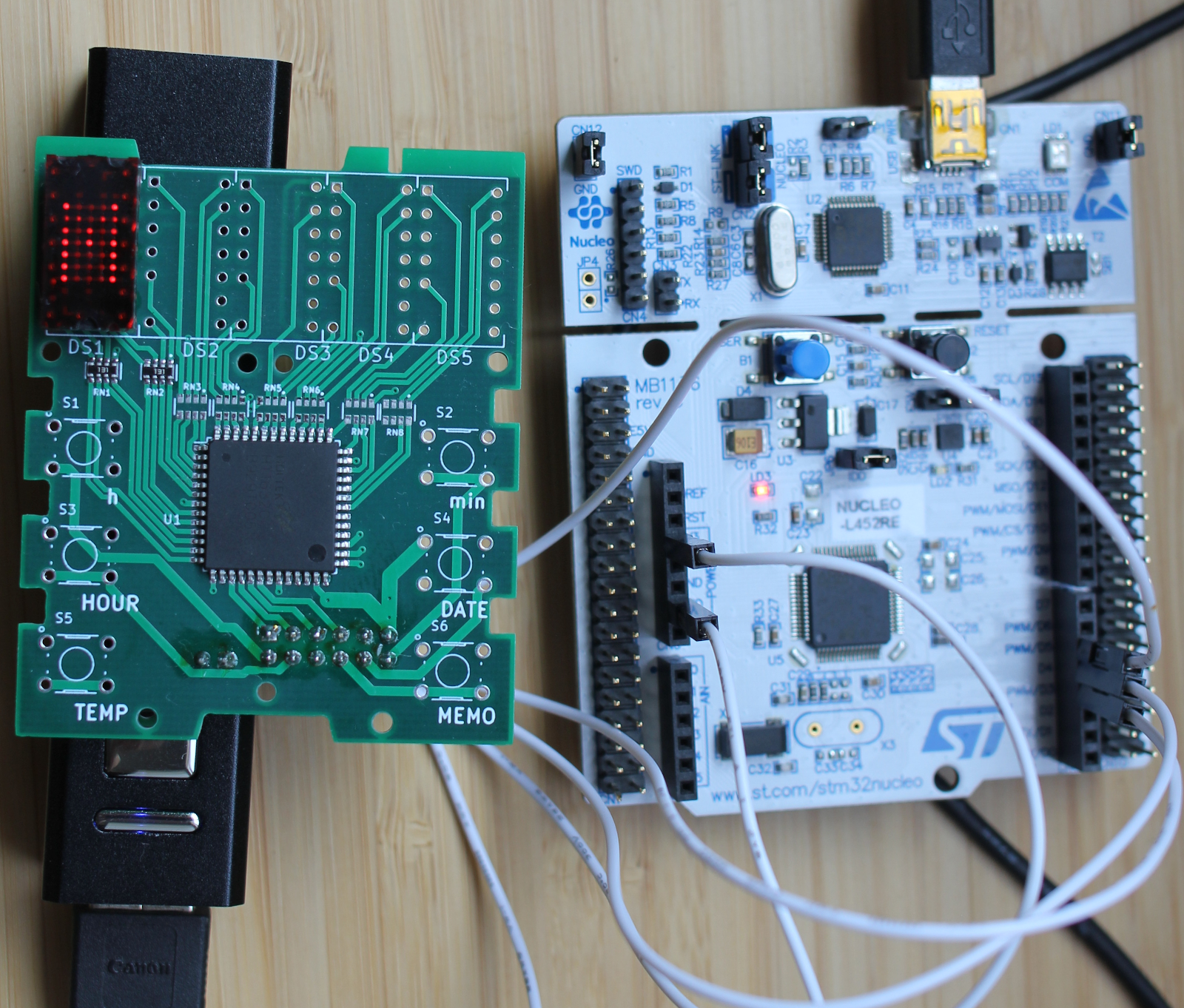
The sample program writes the letter M, changes the brightness, and then makes the HT1632C sleep when CONFIG_PM=y and CONFIG_PM_DEVICE=y in app/prj.conf.
It's interesting to see how the second row of the letter M is half-lighted in the photo. That's because the HT1632C constantly switches ROWs and COMs ON and OFF. The human eye can't catch it, but a photo camera can.