I downloaded an archive for my selected branch of Arduino (version 1.6.3 at the time of writing).
Mighty 1284P: An Arduino core for the ATmega1284P
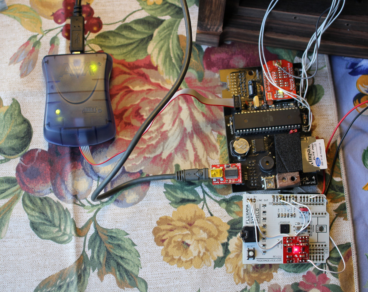
I connected my programmer AVRISP mkII to the ISP header of the board to upload the Arduino bootloader. I also connected the FTDI device to provide the 5V power to the board; otherwise, programming doesn’t work.
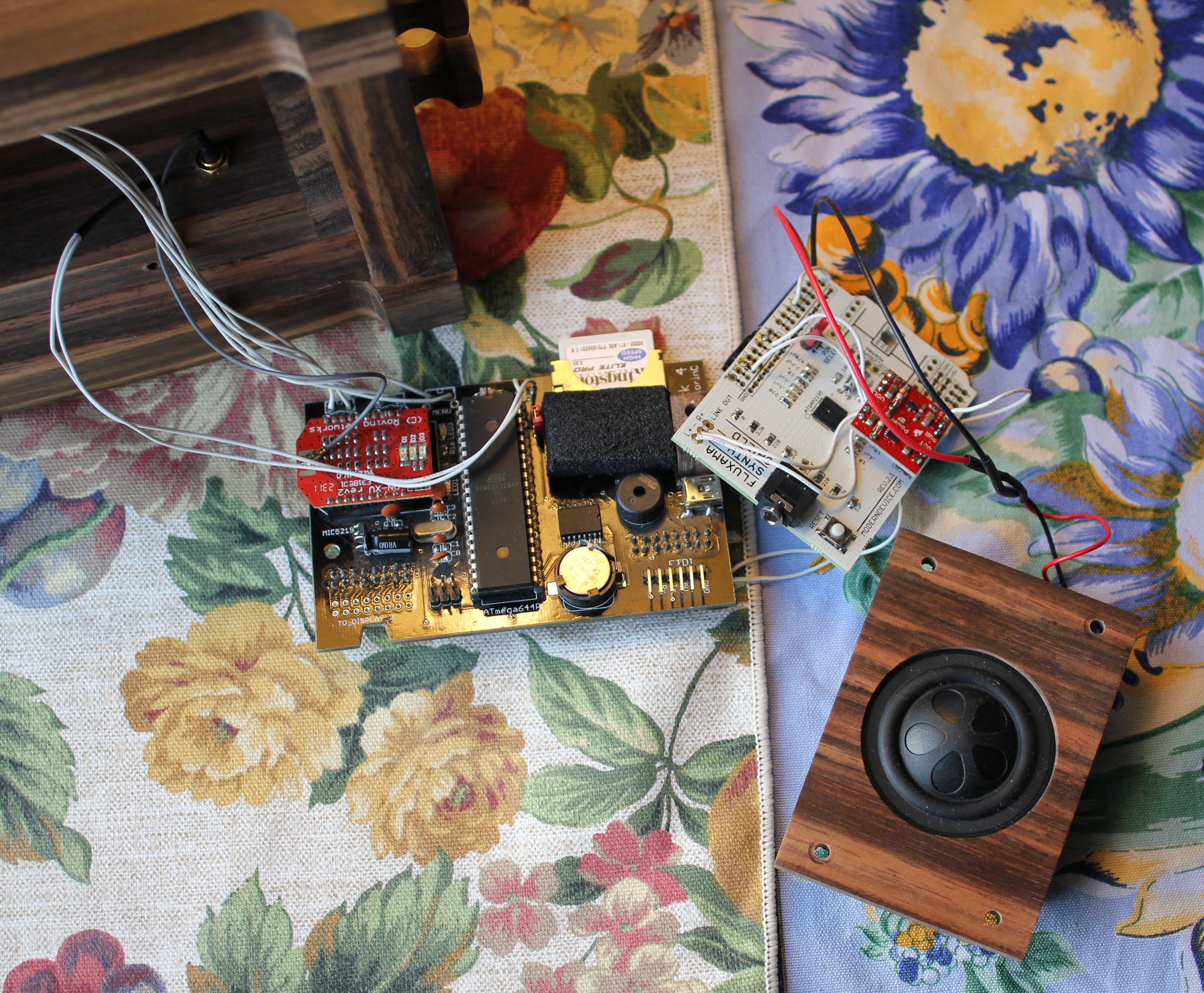
I use the variant of the microcontroller pin definitions “avr_developers”, also known as “sanguino” for my project.
You can find the definitions in the file ~/arduino/hardware/arduino/avr/variants/avr_developers/pins_arduino.h
// ATMEL ATmega1284P (should also work for SANGUINO/ATmega644P)
//
//                       +---\/---+
//           (D 0) PB0  1|        |40  PA0 (AI 0 / D31)
//           (D 1) PB1  2|        |39  PA1 (AI 1 / D30)
//      INT2 (D 2) PB2  3|        |38  PA2 (AI 2 / D29)
//       PWM (D 3) PB3  4|        |37  PA3 (AI 3 / D28)
//    PWM/SS (D 4) PB4  5|        |36  PA4 (AI 4 / D27)
//      MOSI (D 5) PB5  6|        |35  PA5 (AI 5 / D26)
//  PWM/MISO (D 6) PB6  7|        |34  PA6 (AI 6 / D25)
//   PWM/SCK (D 7) PB7  8|        |33  PA7 (AI 7 / D24)
//                 RST  9|        |32  AREF
//                 VCC 10|        |31  GND
//                 GND 11|        |30  AVCC
//               XTAL2 12|        |29  PC7 (D 23)
//               XTAL1 13|        |28  PC6 (D 22)
//      RX0 (D 8)  PD0 14|        |27  PC5 (D 21) TDI
//      TX0 (D 9)  PD1 15|        |26  PC4 (D 20) TDO
// INT0 RX1 (D 10) PD2 16|        |25  PC3 (D 19) TMS
// INT1 TX1 (D 11) PD3 17|        |24  PC2 (D 18) TCK
//      PWM (D 12) PD4 18|        |23  PC1 (D 17) SDA
//      PWM (D 13) PD5 19|        |22  PC0 (D 16) SCL
//      PWM (D 14) PD6 20|        |21  PD7 (D 15) PWM
//                       +--------+
//
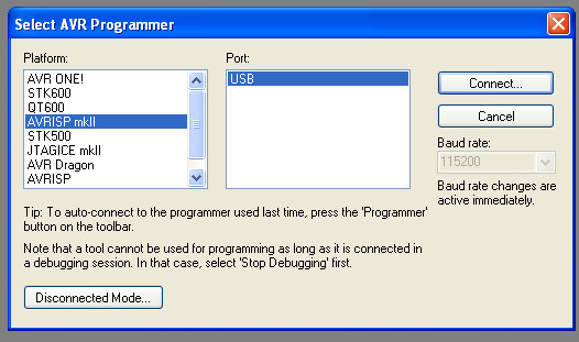
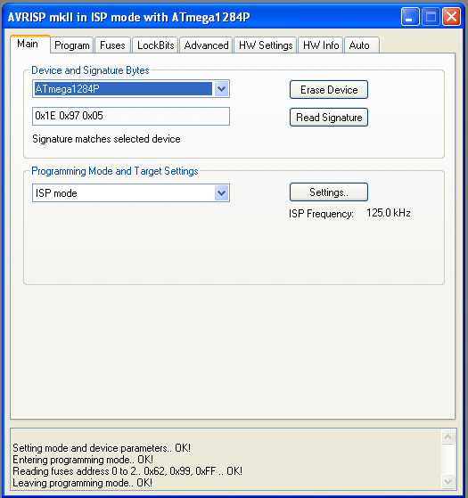
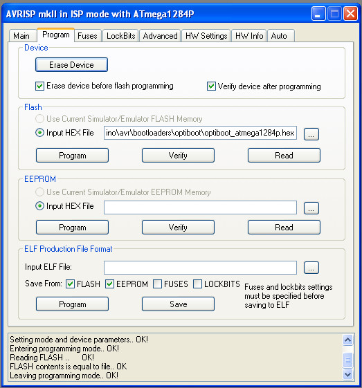
I use my AVRISP mkII programmer to load the bootloader into the microcontroller. I use Atmel AVR Studio (version is 4.19).
I go to Tools -> Program AVR -> Connect. Then I select my programmer.
Then I copy the files from the downloaded archive into the hardware/arduino/avr/ subdirectory of the installed Arduino directory and add the settings for the avr_developers board into boards.txt.
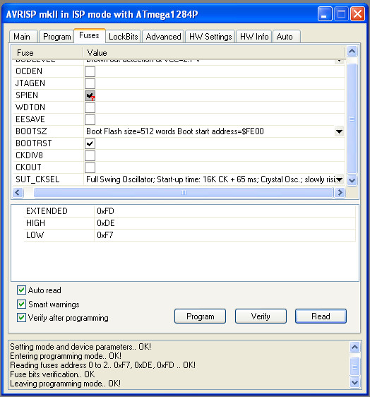
##############################################################

avr_developers.name=avr-developers.com pinouts 16MHz using Optiboot
avr_developers.upload.tool=arduino:avrdude
avr_developers.upload.protocol=arduino
avr_developers.upload.maximum_data_size=16384
avr_developers.upload.maximum_size=130048
avr_developers.upload.speed=115200
avr_developers.bootloader.tool=arduino:avrdude
avr_developers.bootloader.low_fuses=0xf7
avr_developers.bootloader.high_fuses=0xde
avr_developers.bootloader.extended_fuses=0xfd
avr_developers.bootloader.file=optiboot/optiboot_atmega1284p.hex
avr_developers.bootloader.unlock_bits=0x3F
avr_developers.bootloader.lock_bits=0x0F
avr_developers.build.mcu=atmega1284p
avr_developers.build.f_cpu=16000000L
avr_developers.build.core=arduino:arduino
avr_developers.build.variant=avr_developers
avr_developers.build.board=1284P_AVR_DEVELOPERS
After that I select this board in the Arduino IDE: Tools -> Board