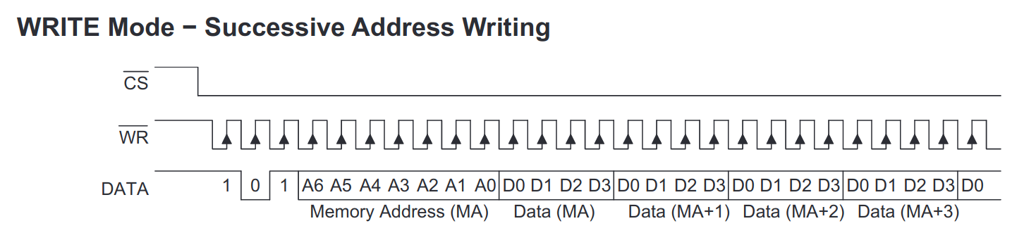
Now, when the HT1632C display driver for Zephyr RTOS is ready, we want to write characters into the display buffer and send the buffer to the LED matrix.
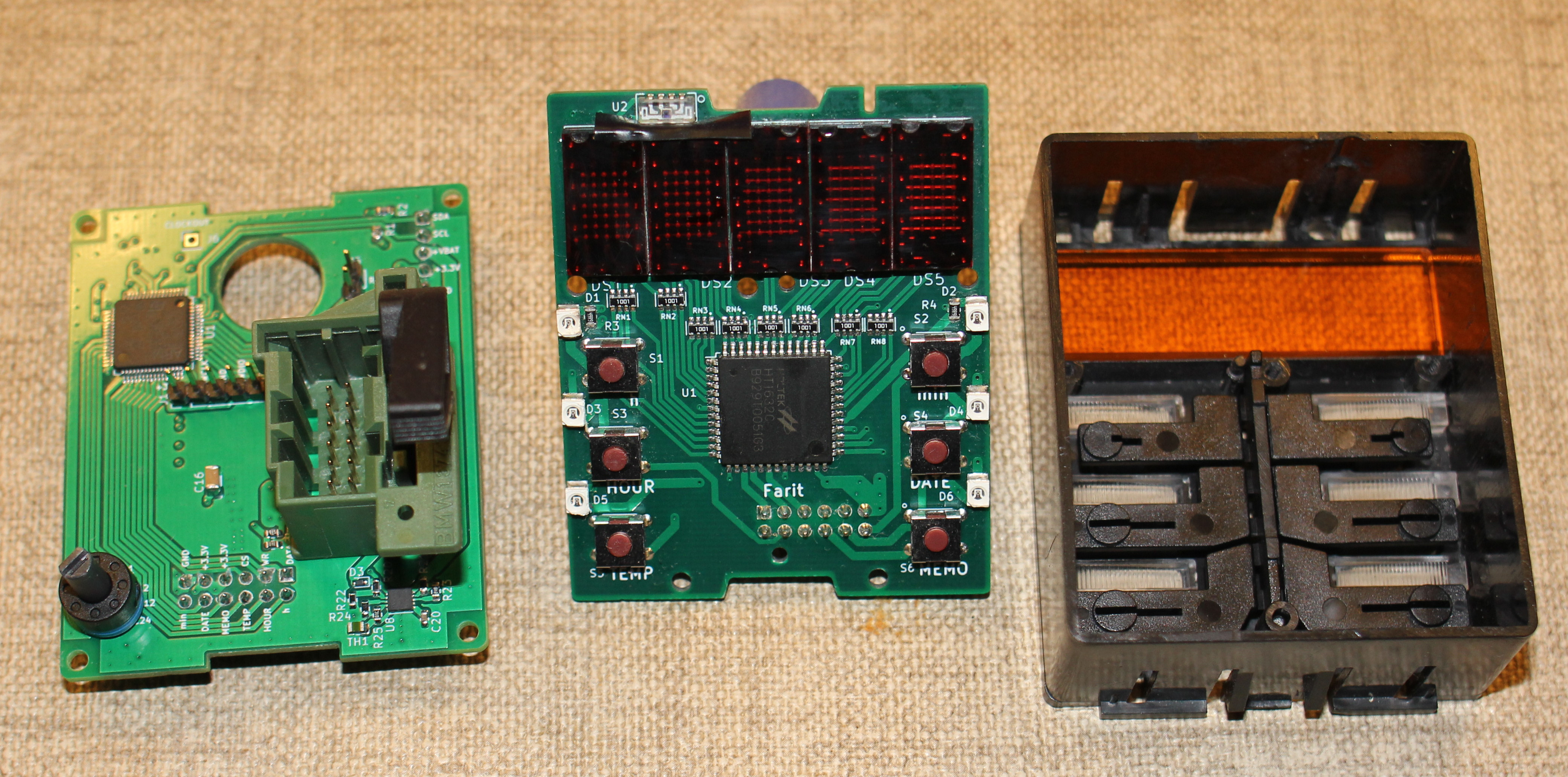
LED matrix
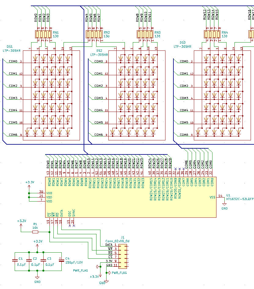
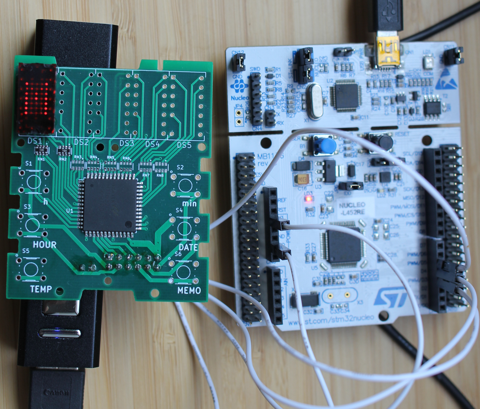
The LED indicator is the LTP-305HR 5×7 dot matrix display. It has an LED for a dot ., that is located at the column 0. So, we will start writing characters at the column 1 of the display buffer.
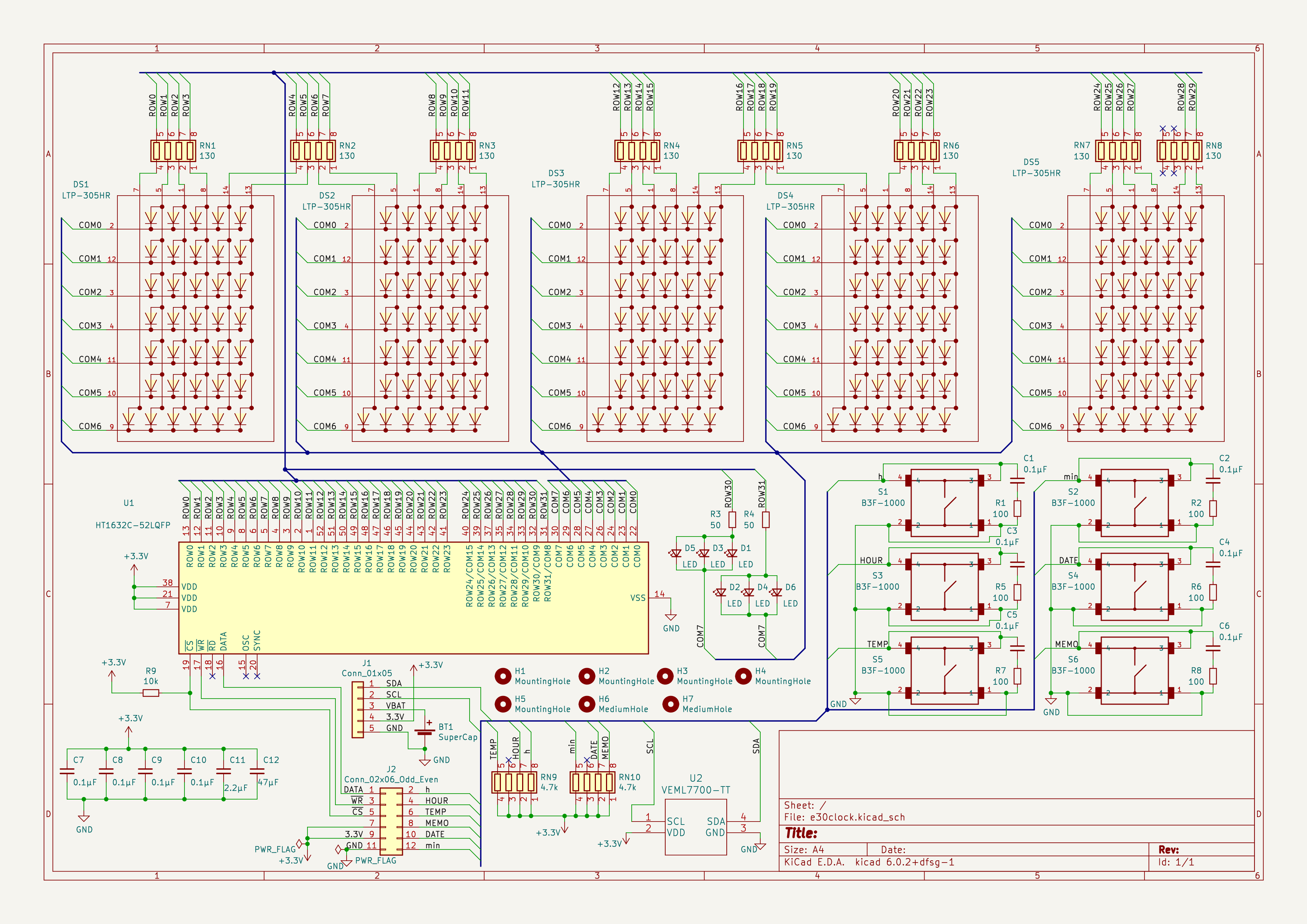
The HT1632C supports 32 ROWs – in our case they will be vertical columns, and 8 COMs – they will be horizontal rows.
The center of coordinates 0x0 starts at the left top.
In our case, we will use 5×7 fixed width fonts. Each character will be represented as an array of 5 uint8_t 8-bit numbers(bytes). The array will start from the leftest column. The top row will start from the most significant(the leftest) bit of a byte.
Here is the letter M displayed on the LED matrix. When a bit is set to 1, it turns on the LED at that position; when it is set to 0, it turns off the LED. The 8th bit doesn’t matter as it’s not displayed at all – we will set it to 0.
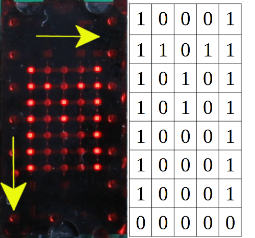
The C array for the letter M looks like this:
{Column 1, Column 2, Column 3, Column 4, Column 5}
{0b11111110, 0b01000000, 0b00110000, 0b01000000, 0b11111110}, // M
Font File
All characters for the 5×7 font are included in the file font_5x7.h
They are located according to the ASCII order starting from the character SPACE ‘ ‘, which has the decimal number 32.
#ifndef FONT_5x7_H
#define FONT_5x7_H

// The width of each font character
#define APP_FONT_WIDTH 5

const uint8_t font[][APP_FONT_WIDTH] = {
    {0b00000000, 0b00000000, 0b00000000, 0b00000000, 0b00000000}, //
    {0b00000000, 0b00000000, 0b11111010, 0b00000000, 0b00000000}, // !
    {0b00000000, 0b11100000, 0b00000000, 0b11100000, 0b00000000}, // "
    {0b00101000, 0b11111110, 0b00101000, 0b11111110, 0b00101000}, // #
    {0b00101000, 0b01010100, 0b11111110, 0b01010100, 0b00101000}, // $
    {0b11000100, 0b11001000, 0b00010000, 0b00100110, 0b01000110}, // %
    {0b01101100, 0b10010010, 0b10101010, 0b01000100, 0b00001010}, // &
    {0b00000000, 0b00000000, 0b11100000, 0b00000000, 0b00000000}, // '
    {0b00000000, 0b00111000, 0b01000100, 0b10000010, 0b00000000}, // (
    {0b00000000, 0b10000010, 0b01000100, 0b00111000, 0b00000000}, // )
    {0b00101000, 0b00010000, 0b01111100, 0b00010000, 0b00101000}, // *
    {0b00010000, 0b00010000, 0b01111100, 0b00010000, 0b00010000}, // +
    {0b00000000, 0b00001010, 0b00001100, 0b00000000, 0b00000000}, // ,
    {0b00010000, 0b00010000, 0b00010000, 0b00010000, 0b00010000}, // -
    {0b00000000, 0b00000110, 0b00000110, 0b00000000, 0b00000000}, // .
    {0b00000100, 0b00001000, 0b00010000, 0b00100000, 0b01000000}, // /
    {0b01111100, 0b10000010, 0b10000010, 0b10000010, 0b01111100}, // 0
    {0b00000000, 0b01000010, 0b11111110, 0b00000010, 0b00000000}, // 1
    {0b01000010, 0b10000110, 0b10001010, 0b10010010, 0b01100010}, // 2
    {0b01000100, 0b10000010, 0b10010010, 0b10010010, 0b01101100}, // 3
    {0b00001000, 0b00011000, 0b00101000, 0b01001000, 0b11111110}, // 4
    {0b11110100, 0b10010010, 0b10010010, 0b10010010, 0b10001100}, // 5
    {0b01111100, 0b10010010, 0b10010010, 0b10010010, 0b01001100}, // 6
    {0b10000000, 0b10001110, 0b10010000, 0b10100000, 0b11000000}, // 7
    {0b01101100, 0b10010010, 0b10010010, 0b10010010, 0b01101100}, // 8
    {0b01100100, 0b10010010, 0b10010010, 0b10010010, 0b01111100}, // 9
    {0b00000000, 0b01101100, 0b01101100, 0b00000000, 0b00000000}, // :
    {0b00000000, 0b01101010, 0b01101100, 0b00000000, 0b00000000}, // ;
    {0b00010000, 0b00101000, 0b01000100, 0b10000010, 0b00000000}, // <
    {0b00101000, 0b00101000, 0b00101000, 0b00101000, 0b00101000}, // =
    {0b10000010, 0b01000100, 0b00101000, 0b00010000, 0b00000000}, // >
    {0b01000000, 0b10000000, 0b10001010, 0b10010000, 0b01100000}, // ?
    {0b01111100, 0b10000010, 0b10011000, 0b10100100, 0b01111000}, // @
    {0b01111110, 0b10010000, 0b10010000, 0b10010000, 0b01111110}, // A
    {0b11111110, 0b10010010, 0b10010010, 0b10010010, 0b01101100}, // B
    {0b01111100, 0b10000010, 0b10000010, 0b10000010, 0b01000100}, // C
    {0b11111110, 0b10000010, 0b10000010, 0b10000010, 0b01111100}, // D
    {0b11111110, 0b10010010, 0b10010010, 0b10010010, 0b10000010}, // E
    {0b11111110, 0b10010000, 0b10010000, 0b10010000, 0b10000000}, // F
    {0b01111100, 0b10000010, 0b10010010, 0b10010010, 0b01011110}, // G
    {0b11111110, 0b00010000, 0b00010000, 0b00010000, 0b11111110}, // H
    {0b00000000, 0b10000010, 0b11111110, 0b10000010, 0b00000000}, // I
    {0b00000100, 0b10000010, 0b10000010, 0b10000010, 0b11111100}, // J
    {0b11111110, 0b00010000, 0b00101000, 0b01000100, 0b10000010}, // K
    {0b11111110, 0b00000010, 0b00000010, 0b00000010, 0b00000010}, // L
    {0b11111110, 0b01000000, 0b00110000, 0b01000000, 0b11111110}, // M
    {0b11111110, 0b00100000, 0b00010000, 0b00001000, 0b11111110}, // N
    {0b01111100, 0b10000010, 0b10000010, 0b10000010, 0b01111100}, // O
    {0b11111110, 0b10010000, 0b10010000, 0b10010000, 0b01100000}, // P
    {0b01111100, 0b10000010, 0b10001010, 0b10000100, 0b01111010}, // Q
    {0b11111110, 0b10010000, 0b10011000, 0b10010100, 0b01100010}, // R
    {0b01100100, 0b10010010, 0b10010010, 0b10010010, 0b01001100}, // S
    {0b10000000, 0b10000000, 0b11111110, 0b10000000, 0b10000000}, // T
    {0b11111100, 0b00000010, 0b00000010, 0b00000010, 0b11111100}, // U
    {0b11111000, 0b00000100, 0b00000010, 0b00000100, 0b11111000}, // V
    {0b11111100, 0b00000010, 0b00111100, 0b00000010, 0b11111100}, // W
    {0b11000110, 0b00101000, 0b00010000, 0b00101000, 0b11000110}, // X
    {0b11100000, 0b00010000, 0b00001110, 0b00010000, 0b11100000}, // Y
    {0b10000110, 0b10001010, 0b10010010, 0b10100010, 0b11000010}, // Z
    {0b00000000, 0b11111110, 0b10000010, 0b00000000, 0b00000000}, // [
    {0b01000000, 0b00100000, 0b00010000, 0b00001000, 0b00000100}, /* \ */
    {0b00000000, 0b10000010, 0b11111110, 0b00000000, 0b00000000}, // ]
    {0b00100000, 0b01000000, 0b10000000, 0b01000000, 0b00100000}, // ^
    {0b00000010, 0b00000010, 0b00000010, 0b00000010, 0b00000010}, // _
    {0b00000000, 0b10000000, 0b01000000, 0b00000000, 0b00000000}, // `
    {0b00000100, 0b00101010, 0b00101010, 0b00101010, 0b00011110}, // a
    {0b11111110, 0b00010010, 0b00100010, 0b00100010, 0b00011100}, // b
    {0b00011100, 0b00100010, 0b00100010, 0b00100010, 0b00000100}, // c
    {0b00011100, 0b00100010, 0b00100010, 0b00010010, 0b11111110}, // d
    {0b00011100, 0b00101010, 0b00101010, 0b00101010, 0b00011000}, // e
    {0b00000000, 0b00010000, 0b01111110, 0b10010000, 0b01000000}, // f
    {0b00010000, 0b00101010, 0b00101010, 0b00101010, 0b00111100}, // g
    {0b11111110, 0b00010000, 0b00100000, 0b00100000, 0b00011110}, // h
    {0b00000000, 0b00100010, 0b10111110, 0b00000010, 0b00000000}, // i
    {0b00000100, 0b00000010, 0b00100010, 0b10111100, 0b00000000}, // j
    {0b11111110, 0b00001000, 0b00010100, 0b00100010, 0b00000000}, // k
    {0b00000000, 0b10000010, 0b11111110, 0b00000010, 0b00000000}, // l
    {0b00111110, 0b00100000, 0b00011110, 0b00100000, 0b00011110}, // m
    {0b00111110, 0b00010000, 0b00100000, 0b00100000, 0b00011110}, // n
    {0b00011100, 0b00100010, 0b00100010, 0b00100010, 0b00011100}, // o
    {0b00111110, 0b00101000, 0b00101000, 0b00101000, 0b00010000}, // p
    {0b00010000, 0b00101000, 0b00101000, 0b00101000, 0b00111110}, // q
    {0b00111110, 0b00010000, 0b00100000, 0b00100000, 0b00010000}, // r
    {0b00010010, 0b00101010, 0b00101010, 0b00101010, 0b00100100}, // s
    {0b00000000, 0b00100000, 0b11111100, 0b00100010, 0b00000100}, // t
    {0b00111100, 0b00000010, 0b00000010, 0b00000100, 0b00111110}, // u
    {0b00111000, 0b00000100, 0b00000010, 0b00000100, 0b00111000}, // v
    {0b00111100, 0b00000010, 0b00001100, 0b00000010, 0b00111100}, // w
    {0b00100010, 0b00010100, 0b00001000, 0b00010100, 0b00100010}, // x
    {0b00110000, 0b00001010, 0b00001010, 0b00001010, 0b00111100}, // y
    {0b00100010, 0b00100110, 0b00101010, 0b00110010, 0b00100010}, // z
    {0b00010000, 0b00010000, 0b01101100, 0b10000010, 0b10000010}, // {
    {0b00000000, 0b00000000, 0b11111110, 0b00000000, 0b00000000}, // |
    {0b10000010, 0b10000010, 0b01101100, 0b00010000, 0b00010000}, // }
    {0b01000000, 0b10000000, 0b01000000, 0b01000000, 0b10000000}, // ~
    {0b00000000, 0b00000000, 0b00000000, 0b00000000, 0b00000000}, // Delete
};

#endif /* FONT_5x7_H */
When we draw a character, we can subtract the value of SPACE ‘ ‘ from its decimal number and find its location in the font array. Then, we write 5 bytes of the font to the buffer.
/**
 * Draws a character at the position X
 *
 * @param uint8_t c The character to display
 * @param uint8_t x The position at the display from which to display
 */
void draw_char(uint8_t buf[], const uint8_t font[][APP_FONT_WIDTH],
               uint8_t c, uint8_t x)
{
    // Convert the character to an index
    c = c & 0x7F;
    if (c < ' ') {
        c = 0;
    } else {
        c -= ' ';
    }

    for (int i = x, j = 0; j < APP_FONT_WIDTH; i++, j++) {
        buf[i] = font[c][j];
    }
}
We can display a character starting from the position 1 like this:
draw_char(buf, font, 'M', 1);
When all required characters are set in the display buffer, the display buffer is sent to the HT1632C controller at once.
display_write(display_dev, 0, 0, &buf_desc, buf);
The code is available on https://github.com/faritka/zephyr-ht1632c